|
|
When you think of clean lines and minimal
ornamentation, the last thing that comes to mind is
traditional design. Unless you're a woodworker, that is.
Those of us who spend our quality time in the shop know
that the Shaker community of the last century pioneered
a style of building that was utilitarian and austere,
yet elegant and classical. It's with these Shaker design
principles in mind that we've created our cherry tall
clock.
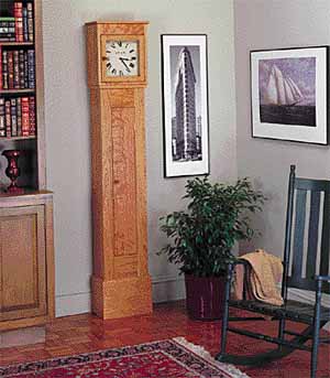
Of course, an antique Shaker clock would be fitted
with a mechanical movement, complete with pendulum
hanging in the long case. To simplify and update
construction, we installed a quartz clock movement.
Our clock case is constructed of solid cherry, with
the back panels and clockface panel of 1/4-in. plywood.
Because it may be hard to find wide cherry boards at a
reasonable price, be prepared to purchase narrow stock
and laminate wider pieces where
necessary. | |
|
|
|
|
|
Case Construction
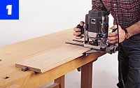
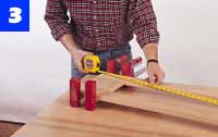
The first step is to glue up narrow stock to produce the
wider components. Rip and crosscut the pieces slightly
oversize, and use a jointer or hand plane to true the mating
edges of each piece. Cut joining-plate slots along the edges,
about 8 in. on center. Apply glue to the slots, plates and
mating edges of each panel assembly, install clamps and let
the glue dry for 20 to 30 minutes before scraping off the
excess. When the glue has dried, rip and crosscut the wide
panels to finished dimension. |
|
|
|
|
|
|
|
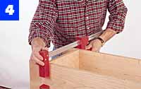
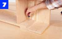
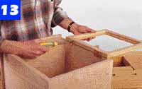
| Assemble the
long center case by joining the top and bottom panels to
the case sides. Clamp until the glue
dries. | |
|
|
|
|
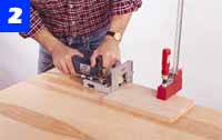
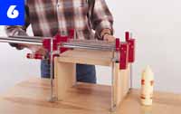
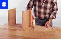
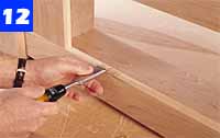
| After cutting
the plate slots, apply glue to the joint edges, plates
and slots. Then, clamp in two directions to align the
pieces. | |
|
|
|
|
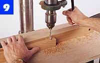
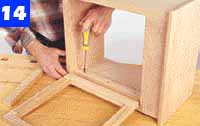
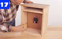
| Attach the
cleats to the top case with screws. Countersink the
pilot holes so screwheads fall below the wood
surface. | |
|
|
|
|
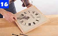
| Screw the
completed clockface panel to the back edges of the
upper-case cleats using 3/4-in. No. 8 rh
woodscrews. | |
|
|
|
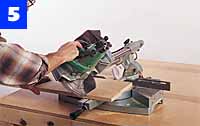
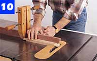
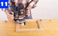
Cut strips of 3/8 x 1-in. cherry for the molding
under the top case. Round one edge of each strip on a
router table, using a featherboard to hold the strip
against the fence. Miter the molding to length and
install it with 1-in. brads, using glue at the miter
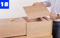
joints. Set the brads and fill. Cut 1/4-in. plywood
panels for the upper and lower case backs and install
each with 3/4-in. No. 8 rh screws (Photo 18).
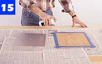
Before finishing the clock, remove the back panels
and clockface. Also, prepare the stops for holding the
glass panel in the door. Bore and countersink pilot
holes for screws, but don't install the glass until
after finishing. Bore holes for the doorknobs and glue
them in place.
Sand all case parts with 120-, 150-, 180- and
220-grit sandpaper. We completed our clock with several
coats of a penetrating oil finish. Apply the finish
according to the instructions. After the final coat has
cured, reinstall the clockface and case backs, mount the
glass in the upper door and hang the doors.
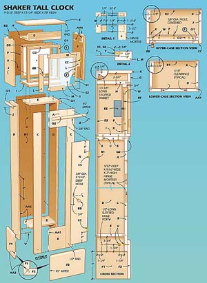
| MATERIALS LIST--CLOCK |
| A |
1 |
13/16 x
6 x 6 5/8" cherry (top rail) |
| B |
1 |
1 3/16 x
6 5/8 x 9" cherry (bottom rail) |
| C |
2 |
13/16 x
3 x 54" cherry (stile) |
| D |
2 |
13/16 x
7 3/16 x 54" cherry (side) |
| E |
2 |
13/16 x
6 15/16 x 11" cherry (bottom/top) |
| F1 |
2 |
13/16 x
8 13/16 x 10" cherry (base side) |
| F2 |
1 |
13/16 x
10 x 14 1/4" cherry (base front) |
| G |
1 |
13/16 x
2 3/4 x 12 5/8" cherry (upper rail) |
| H |
1 |
13/16 x
7 3/4 x 12 5/8" cherry (inner top) |
| I |
1 |
13/16 x
8 9/16 x 12 5/8" cherry (top base) |
| J |
2 |
13/16 x
8 13/16 x 16 3/16" cherry (top side) |
| K |
1 |
13/16 x
9 5/16 x 15 1/4" cherry (outer top) |
| L |
2 |
13/16 x
1 1/2 x 12 1/2" cherry (door stile) |
| M |
2 |
13/16 x
1 1/2 x 11 1/2" cherry (door rail) |
| N |
1 |
13/16 x
6 1/2 x 38 7/8" cherry (lower door) |
| O1 |
2 |
13/16 x
1 1/4 x 12 5/8" cherry (stile cleat) |
| O2 |
2 |
13/16 x
1 1/4 x 11" cherry (rail cleat) |
| P |
1 |
1/4 x 12
5/8 x 12 5/8" plywood (clockface panel) |
| Q1 |
2 |
3/8 x 1
x 8 3/8" cherry (side molding) |
| Q2 |
1 |
3/8 x 1
x 13 3/8" cherry (front molding) |
| R1 |
1 |
1/4 x 12
1/8 x 50 1/4" cherry (lower back) |
| R2 |
1 |
1/4 x 13
3/4 x 16 11/16" cherry (upper back) |
| S1 |
2 |
3/8 x
3/8 x 10 1/4" cherry (glass stop) |
| S2 |
2 |
3/8 x
3/8 x 9 1/2" cherry (glass stop) |
| T |
1 |
1/8 x 10
3/16 x 10 3/16" glass (pane) |
| U |
4 |
1 1/2
No. 8 fh brass screw |
| V |
6 |
1 1/2
No. 8 rh brass screw and washer |
| W |
12 |
1 1/4
No. 8 fh brass screw |
| X |
28 |
3/4 No.
8 rh brass screw |
| Y |
12 |
3/4 No.
4 fh brass screw |
| Z |
as
reqd. |
1"
brad |
| AA1 |
48 |
No. 20
joining plate |
| AA2 |
4 |
No. 0
joining plate |
| BB |
2 |
7/8"-dia. Shaker knob, No.
76KW15* |
| CC |
2 |
pair
11/4 x 2" brass hinges, No. 107H6P* |
| DD |
1 |
clockface, No. 7415S** |
| EE |
1 |
clock
movement, No. 00047** |
| FF |
1 |
clock
hand set, No. 4870X** |
| Misc.: Spray adhesive; glue; 120-, 150-,
180- and 220-grit sandpaper; 4/0 steel wool; oil
finish. |
| *Available from Whitechapel Ltd., P.O.
Box 11719, Jackson, WY 83002; 800-468-5534. |
| ** Available from Woodcraft Supply, 210
Wood County Industrial Park, P.O. Box 1686,
Parkersburg, WV
26102. | |
|
|
| Install the
plywood backs. The upper back panel can be easily
removed for access to the movement or to change
batteries. | |
|
|