
David Lucas shows how to make his version of this
timeless game that will appeal to people of all ages
 One of
the joys of having young grandchildren is that you can again indulge in
those pastimes that had to be abandoned as one's own children grew up. So
you can decide for yourself whether the game described here is more for them
or for me! One of
the joys of having young grandchildren is that you can again indulge in
those pastimes that had to be abandoned as one's own children grew up. So
you can decide for yourself whether the game described here is more for them
or for me!
|
| |
|
The Top Arch |
 |
 |
|
This is one of the key components of the construction.
First I tried to make the sides come to a feather edge but these crumpled,
so I redesigned it to give a substantial (1/4in - 6.4mm) edge instead. This
involved adding the internal side strips to the design to give a smooth
inner surface.
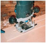
The arch is cut from a 14 1/4in (362mm) square of 3/4in (19.1mm) MDF. Now
I was planning to make two versions of the game so I needed two arches both
of which were cut from the one square; if, however, you only want to make
one version, a semi-circular arch could be cut from a piece of MDF 14 1/4in
(362 mm) x 8in (203mm) approx., just deep enough to allow for the beam
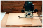
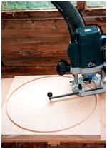
trammel hole. This hole is drilled centrally in the square or central and 7
1/8 (181mm) from one long side of the rectangle and with a diameter which
just accepts the pin of the beam trammel. A straight cutter is used in the
router and the beam trammel is adjusted until the outer edge of the cutter
is 6 7/8in (174.6mm) from the pin. The cutter diameter is not, therefore,
significant. The block of MDF is fastened to a scrap board with double-sided
adhesive tape, making sure that the tape holds both the centre disc and the
outer part of the block. The cut is then made, gradually deepening the
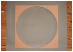
setting of the cutter until the block is cut right through. The arch is then
completed by gently sawing the outer part of the MDF block into two or
trimming to size if only one has been made. |
| |
|
The Base |
|
 |
|
The base is cut to size from a sheet of 3/8in (9.5mm) MDF and the three
grooves are cut to receive the inner strips. These grooves are 3/8in (9.5mm)
wide and 1/8in (3.2mm) deep and positioned as shown in fig 1, (remember that
the base is 1/4in (6.4mm) smaller than the outer frame on all four sides).
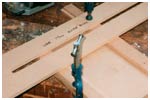
To cut them a simple jig is used, being a long strip of 3/8in (9.5mm) MDF
with a slot cut to just receive a 17mm guide bush. The position of the
grooves is marked on the base and the jig carefully placed symmetrically
over them and held with a G-clamp which can itself be held in the bench
vice. A 3/8in (9.5mm) straight cutter is used in the router. The groove
parallel to the sides should be machined first and then the other two can be
cut, parallel to the ends, from the first groove to the appropriate edge. |
| |
|
The Sides |
|
 |
|
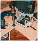
These are cut to size and a rebate 3/8in (9.5mm) high and
1/8in (3.2mm) deep is cut along the bottom to receive the base. I used a
1/8in (3.2mm) slotting cutter with a bearing chosen to give 3/8in (9.5mm)
depth of cut, with the router in a table and the MDF strip lying flat on the
table, but other cutters, e.g. a rebater or even a straight cutter, could be
used. A vertical groove, again 3/8in (9.5mm) wide and 1/8in (3.2mm) deep is
cut 1 1/8in (28.6mm) in from the bottom end on the left hand side. For this
the same jig as described above is used with the side clamped to a piece of
scrap MDF and the jig clamped to the same piece of scrap (plus a 3/8in
(9.5mm) thick spacer, again of scrap MDF) and running across the side at
right angles. Unfortunately this jig was not wide enough to clamp directly
as the clamp prevented full movement of the router - since then I have made
a shorter but wider slot jig that can be clamped directly to the side. A
similar groove is required in the right hand side but placed 2 7/8in (73mm)
from the end. (Note: This position may have to be changed slightly - see
discussion under 'firing mechanism').
Both ends of each side are mitred. A 45° bevel cutter is used in the
router with the router in the table. Another simple jig, a rectangular piece
of scrap MDF 1/2in (12.7mm) thick with a 45° bevel cut to a depth of 3/8in
(9.5mm) across one end is used to guide the ends across the cutter. If no
guide is used there is nothing for the side to bear on once the end has been
reduced to a feather edge. The side and jig are held next to each other by
hand pressure and the height of the cutter increased step by step until the
bevel is complete. It will save a lot of cutter adjustment if both sides,
the top and the bottom are all machined step by step at the same time. Both
top edges of each side are rounded over using an 1/8in (3.2mm) radius
rounding over cutter. |
| |
|
The Top |
|
| |
|
This needs both ends mitred, a groove for the base and the
top edges rounding over in the same way as for the sides. |
| |
|
The Bottom |
|
| |
|
This also needs the same machining as for the top. In
addition a vertical groove 3/8in (9.5mm) wide and 1/8in (3.2mm) deep is cut
1 1/2in (38.1mm) in from the right hand end. (Note: All the vertical grooves
on the bottom and sides should match the horizontal grooves on the base).
Then a horizontal groove 1/8in (3.2mm) wide and 1/8in (3.2mm) deep is cut
1/4in (6.4mm) down from the top from the left hand end to the vertical
groove, to form a slot for the sliding lid of the 'ball park'. |
| |
|
Inner Strips |
|
| |
|
The one running parallel to the sides, and so forming one
side of the firing shute, needs two vertical grooves, of the standard size,
to receive one end of each of the other two strips. It also has to have part
of the bottom end cut away just to clear the corner brace of the firing
mechanism. Both top edges are rounded over on all three inner strips. A
horizontal groove to match that on the bottom is cut along the long inner
strip which runs parallel to the bottom. |
| |
|
Inner Sides |
|
| |
|
These are cut to size but may need slight adjustment to fit
between the top arch and the appropriate inner strip. They are cut from
1/4in (6.4mm) MDF rather than 3/4in (19.1mm) so that the smooth face of the
MDF is vertical. The join between the arch and the right hand inner strip in
particular must be smooth so that the balls are not deflected from their
path around the arch. |
| |
|
Inner Lid |
|
| |
|
This slides in the grooves cut either side of the 'ball
park'. The strip of MDF is rebated to a depth of 1/8in (3.2mm) to leave a
tongue just under 1/8in (3.2mm) thick so that, even when painted, it will
slide in the grooves. The left hand side must be cut down by 3/8in (9.5mm)
for the first 1 1/4in (31.8mm) to allow entrance for the lid. You may also
wish to trim the left hand mitre on the bottom in the same way for neatness.
A small square of MDF is stuck onto the end of the lid to form a simple
knob. |
| |
|
The Firing Mechanism |
|
 |
|
This is the most important part of the project, yet one
which I wanted to keep as simple as possible. The very first thing to do is
to find an appropriate spring or springs. They must be compression springs
of a sensible size, fitting round the 1/4in (6.4mm) steel rod and strong
enough to fire the balls to the top of the arch and yet not too strong for
children to pull back. I conducted trials by asking my grandchildren if they
could squash a spring I judged strong enough.
The 1in (25.4mm) long springs I finally used came from a Screwfix pack of
compression springs but this would be a very expensive source if you didn't
need a general supply. Maybe the 'bit-box' will provide what you need. The
dimensions of the firing mechanism may have to be slightly modified to suit.
I also thought that repeated use might well pull the corner woodwork apart
despite the strength of modern glues, so, from the start I decided that the
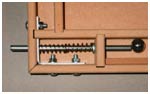
corner must be reinforced. It turned out that a Screwfix 50mm corner brace
was ideal; if one of the holes nearer to the corner is carefully drilled out
to 17/64in (6.7mm) (to allow free movement of the 1/4in (6.4mm) rod) then it
came in just the right position. The corner brace was checked (and adjusted)
for a true 90° angle and fixed in place with 3 M5 20mm pan head machine
screws, washers and nuts. The height of the main hole was correct if the
brace rested on the base. Appropriate holes must be drilled in the right
hand side, in the bottom and in the short inner strip to match. The rod must
be long enough so that when the assembly is pulled right back it does not
come out of the hole in the short inner strip. A commercial wooden drawer
knob was drilled out and stuck onto the outer end of the rod.
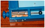
The firing mechanism underwent further development! Mark 1 used a washer
on the rod, above the two springs, held in place by superglue, and omitted
the loose washer between the springs. This was not successful as the washer
eventually came loose and the springs twisted into each other. Mark 2
replaced the washer with an M6 nut drilled out to slide onto the rod and
fixed in place with epoxy-resin adhesive. A loose washer was also added
between the springs. This worked well but could not be removed if anything
went wrong after assembly - without demolition that is! So in Mark 3 a small
hole was drilled through the firing rod above the nut position and a small
panel pin inserted and bent over. So far both Mark 2 (blue version) and Mark
3 (grey version) have been successful. A small piece of MDF is screwed to
the right hand side to cover the spring mechanism. |
| |
|
Painting |
|
| |
|
Each piece is painted before assembly. This avoids the
problems of getting a clear separation between the two colours and of
getting paint on the panel pins. Each piece was marked so that areas later
to be glued were not painted - quite a fiddly business in itself. |
| |
|
Pinning |
|
 |
|
I used 25mm brass panel pins, again from Screwfix. The
number needed will depend on the pattern used but 250g will give about 600
pins which should be more than sufficient for any one board. In order to get
an even spacing and height for the large cups a very simple jig is used
consisting of a small piece of 3/4in (19.1mm) MDF with two holes drilled in
it. The diameter of the holes must be just enough to clear the head of the
panel pins and the holes are set 1/4in (6.4mm) in from the edge of the piece
of MDF. The distance apart of the holes is equal to the radius of the cup
required. I used 1 1/2in (38.1mm) for the larger cups and 1/2in (12.7mm) for
the smaller, top one. Then the positions of the pins at the centre of the
semi-circles are carefully marked on the painted base and the pin driven in
using the jig to control the height. Then the jig is positioned over the
central pin so that the other hole, for the outermost pin, is in position
and this second pin is hammered in. The jig is then lifted off, replaced
over the central pin and butted against the second pin and the third pin
driven in, etc. This gave reasonable semi-circles and reasonably upright
pins although one or two might need a tweak with the pliers. The smaller cup
is made in the same way although the central pin is removed to allow entry.
The bottom of the base is divided into five parts, using another piece of
MDF with one hole 1/4in (6.4mm) in from the end to space the pins, butting
it against the previous pin each time. A few single pins are added at
strategic places to keep the path of the balls in doubt, the most important
of these being the one at the left hand end of the top arch. This will be
struck by all the faster-moving balls and they will rebound from it on their
journeys.
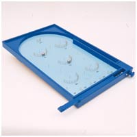
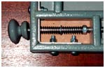
The pattern of pinning is a matter of choice as you can see from the two
examples I have made. It is simpler in the blue one and more complex in the
grey with semi-circles in semi-circles and divided semi-circles but the same
principles apply. Some bagatelle games have small cups, to accept but one
ball, drilled out from the base but I did not incorporate this idea. |
| |
|
Finishing |
|
| |
|
The various parts are now glued together, the firing
mechanism being installed at the same time (mark 2) or later (mark 3). A
block is placed under the base to tilt it being glued 5in (127mm) from the
top (but this should be tested by experiment first as it may be affected by
spring strength). Four rubber feet are then screwed in place, two near the
bottom corners and two on the block under the base. These should prevent
scratching of the surface on which the game is played and give the game a
more stable position.
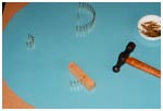
Finally a large number of balls are fired to see which cups are favoured
and which are more difficult, so that a suitable numbering system could be
devised. My wife then added these numbers with a marker pen. 10 steel balls
(or more) 5/8in (15.9mm) in diameter are placed in the ball park. These
balls, known as 'small steelies', come from a marble supply shop. The game
is now ready for use. |
| |
|
Cutting List |
|