Bombe Vitrine
Compound Curve Cope and Stick Router Techniques
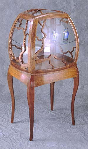 'Bombe' is a French
term, it means 'rounded' and has been used to refer to a variety of furniture
designs. 'Vitrine' is French too, it comes from the Latin 'vitrum' meaning
glass. A vitrine is a fine glass display case.
'Bombe' is a French
term, it means 'rounded' and has been used to refer to a variety of furniture
designs. 'Vitrine' is French too, it comes from the Latin 'vitrum' meaning
glass. A vitrine is a fine glass display case.
Have you ever had an idea that you couldn’t
shake off, demanding that you give it a try? That’s what I went through for
many years before undertaking this rather time-consuming project. From the
start of my woodworking career I was more interested with curved work than
rectilinear, and this project carries that interest to one of its further of
possible manifestations. This project began with a desire to produce a rounded,
organic form not limited by the rectilinear requirements of standard
woodworking tooling. Though the project carried me far afield with geometric
abstraction, my original intention was not to create complex techniques purely
for their own merit, intriquing as they may be. The intention was to make a
fairly simple form, but it so happened that the techniques required became
rather involved.
It’s fairly easy to put a single curve into a
woodworking design, such as a curved top rail on a flat cabinet door. Going one
step further, you can fairly easily bow the door, that is, make it curved back
and forth but still straight up and down, requiring single bent glass. Note,
though, that if you both bow the door and put a curve into the top rail that
the top rail now has two curves in it, and qualifies as a compound or complex
curve. You’ll find fascinating treatments of techniques for this kind of work
in "Circular Work in Carpentry and
Joinery", by George Collings. Click on the book name to see more about it.
A bowed door, with a curve top rail or not, has
a cylindrical shape, which is to say that you can think of it as a section of a
larger cylinder. The next step geometrically is to move from a cylinder to a
sphere, as does my bombe vitrine. The glazed frames on this cabinet are sphere
sections, which proceed from specific radii. Other more complicated forms are
possible (some of which have been done) which involve either free sculpting or
more complicated geometrical designs such as ellipses or differing curves on
different axes (a sphere, by definition, has the same curve on all axes).
One general rule applies. The more complex your
design the more time consuming and difficult it will be to make. The bombe
vitrine shown here took a total of about 1350 hours to complete. If you want to
take on a project like this, settle in for the long haul- you won’t be done by
Christmas.
This treatment of the processes I went through
to build this cabinet does not contain specific instructions for building the
cabinet shown. I’m not trying to protect the design, but I doubt that anyone
will try to make a duplicate of this one and you probably don’t want that level
of detail. This treatment just shows you the major techniques used in spherical
cope and stick router work, and points you toward the complexities involved
with designing such a piece of furniture. If you really intend to build
something like this, contact me and I’ll try to persuade you not to. For your
sake, believe me. If you persist, I’ll help you with design specifics to a
certain extent if you are easy to work with. I’d like to see someone try
this, but not if they end up frustrated.
WHEN WORLDS COLLIDE- THE PLANE OF INTERSECTING
SPHERES
When two planets smack together, they explode.
I know, cause I saw it on TV once. But, when two imaginary spheres come
together, they intersect in three dimensions like two large soap bubbles
joining together in some sort of ethereal geometric bliss.
|
|
|
To understand what it takes to assemble a
construction designed as sections of spheres, you must be able to visualize
what happens when spheres intersect (see drawing 1). You must know where the
radius center of each sphere is in relation to the other sphere center. To
figure how I would join the sides of this cabinet, I made a full scale section
drawing of a horizontal plane through the widest part of the upper cabinet as
in drawing 2. (The sphere centers lie on this plane.) This drawing forced me to
decide which radii I would use for the piece, and where the sphere centers were
located on the X and Y axes. Later alignment of the outer frame parts as they
were made in the router jigs depended entirely upon this drawing and others
similar to it.
|
|
Think about those soap bubbles again. Floating
apart in the air, each is a separate sphere. But when they contact, a flat area
of soap membrane resides within the circle that is created where the two
spheres contact. If the bubbles are true spheres, the circle of contact will be
a true circle, and this circle will describe a flat plane. This is the plane of
intersecting spheres and is the only flat surface you have to refer to in
design and construction of such a piece.
Note that the horizontal plane I used to draw
the X and Y axes, the sphere centers and the cabinet parts (drawing 2) is not
the same plane as the plane(s) of intersecting spheres. At each of the four
corners of the cabinet, and at each of the four sides of the top where it
intersects the sides below, a different plane of intersecting spheres is
described. Each of these planes must be plotted in relation to the centers
of the spheres it involves. You must know where the planes of intersecting
spheres are in relation to the sphere centers and cabinet central axes in order
to be able to align components in the router jigs for shaping. One critical
piece of information I used is the fact that when you are dealing with
intersecting spheres of equal radius, the plane of intersecting spheres must
pass through the midpoint of a line drawn between the sphere centers.
Confused? Well so was I, and for months. I
racked my neurons for weeks over some of these three dimensional convolutions,
and spent a few sleepless nights where I finally realized a solution at 3AM,
thus allowing me to sleep. Finally, however, I concluded that it is really very
basic three-dimensional geometry- just a bunch of spheres and planes bumping
into each other at specific angles and with specific radii. The problem is that
the human brain prefers two dimensional, linear problems rather than
three-dimensional curve balls. But, once you get used to visualizing the parts
involved you’ll find that the basic geometric relationships are simple. Making
drawings helps a great deal to conceptualize what’s happening, as well.
Though it's possible to make many of
these geometric situations very complicated with algebra and calculus, it's
also unnecessary. My approach was pragmatic and physical- I did what I
needed in order to make the router move along the shape required. I used
geometric abstraction only as far as I needed to in order to learn how to
arrange my jigging such that it would produce parts that fit. I was not so much
concerned with making the cabinet parts fit a rational abstraction perfectly as
I was determined to make the cabinet parts fit each other practically.
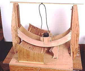
BUILDING THE JIGS
When you use a router table with flat stock,
you use a flat router table. When you do router work on spherical pieces, you
need spherical surfaces to place your work upon. With a flat router table and
flat work, when you want to flip the part and put the opposite face on the
table you use the same table. With spherical parts you must make two jigs- one
that is domed and one that is dished. You work on the outside of spherical
parts on the dome jig, and work on the inside on the dish jig. See photos ahead to look at these jigs.
|
|
These jigs are somewhat time consuming to make
but you will spend far more time using them than making them. The ultimate
accuracy of your work will be a function of the accuracy of your jigs, so it is
wise to build them well. But, know where you must be accurate and where it
doesn’t matter. The accuracy of the dome and dish jigs depends on how well the
spherical surface is cut into them, that is, how close it is to a true sphere.
As well, the accuracy of these jigs depends upon how rigid the structures are
that suspend the router above the work. Great care in locating the pivot points
for the swinging template arms and making them and their supports rigid is
necessary. It is not necessary to make the dome and dish glue blanks all that
accurate up to the point of glue up. They just need to be close enough to the
required shape that the router can cut the required sphere section into them. They are carving blanks.
|
|
The flat surface beneath the dish jig needs to
be flat and rigid, because special jigs that hold parts during the first
shaping cut must be located on this surface. The surface to which the dome jig
is attached doesn’t need to be flat because the only thing that gets attached
to it is the dome jig itself. However if it is terribly out of flat you will
have difficulty aligning the pivots for the template arms
|
|
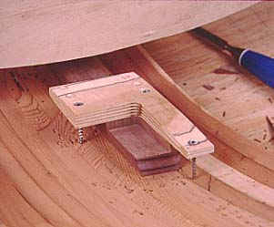
Photo 3- Scribing the
different radii of each part onto the plates. |
Use a stable wood for the dome and dish jigs,
so that once you have cut out the spherical shapes into them they will be less
likely to distort with moisture variations in the air. I used recycled redwood
fencing for mine. This old growth redwood, pulled out of the
|
|
Back to conceptualizing about spheres so we can
figure out how to make the pieces that go into the dome and dish blanks.
Imagine a four foot diameter sphere with a flat, horizontal plane passing
through the middle of it (drawing 3). Now, imagine parallel planes spaced at 3
inches from the first, both above and below it.
|
|
Continue adding such planes until there are
enough to fill the inside of the sphere. Note that the first plane contacts the
sphere at a tangent that is 90o to the plane. But the planes adjacent to the
first plane contact at a tangent with an
|
|
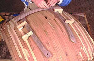
Photo 5- Gluing the
cutoffs onto other plates made my use of the material more efficient. |
angle less than 90o. The further each plane is
from the center plane, the less the angle is of its tangent to the circle. From
this we see that each successive layer of the glue up lamination for each of the
dome and dish jigs must be cut at a different angle than the last.
As well, each successive layer must be cut at a
different radius, because the circle described by that layer has a smaller
circle radius to the Y axis, even though that circle has always the same sphere
radius as the other circles to the sphere center.
|
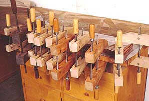
|
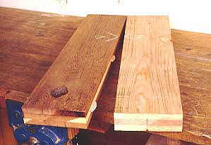
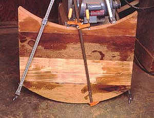
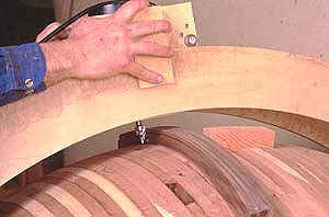
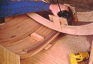
I began my jigs by gluing together three pieces of 1x fencing as in photo 1. First I planed the fencing so it would glue well and to make the pieces uniform in thickness. After laminating the groups of three together, I edge glued them together to make large plates as in photo 2. I made a full scale section drawing through each jig to show me the angles and radii required for each as in drawing 3, then began scribing the radii onto the large blanks with shop-made trammel points as in photo 3. Next came band sawing each of the laminations out as in photo 4. For efficiency I glued the off-cuts onto other blanks as in photo 5.
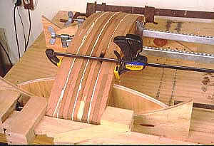
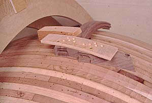
Photo 6 shows the first glue up for the dish
jig. It gets glued up in an upside-down position so that the critical inside
surface can lie on two special plywood reference jigs during the glue up. Those
jigs hold each of the laminations in correct relation to each other so the end
result approximates the sphere required. The radius of those jigs is a function
of how far apart they are from each other, just as the radius of each
lamination is a function of how far they are from the central plane, as
explained above.
|
|
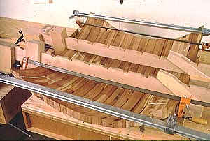
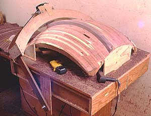
Photo 7 shows the first glue up of the dome
jig, again upside down so that the surface of the jig that we want to use is
the one that contacts the reference jigs. After that dried I glued on two more
laminations on each side, after that dried two more went onto each side as in
photo 8. I made two domes, one for the router jig and one to use as an assembly
table to glue the frames together on.
|
|
MAKING
THE TEMPLATE ARMS
You’ll see from the photos that the routers sit
in little carriages that ride on curved templates with small bearings. The
radii of these templates is greater or lesser than the radius of cut required,
by however much was required for the router carriage. For rigidity I made the
templates six inches wide and used Ѕ" thick birch
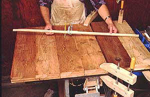
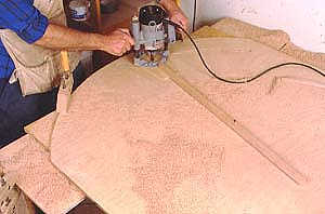
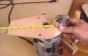
plywood. I swung the arcs on the templates using a router arcing setup as in
photo 9. To do so you must very carefully measure the distance from the pivot
point of the arcing jig (just a nail or screw) to the bit as in photo 10.
Measure to the outside of the bit for an inside curve, and to the inside of the
bit for an outside curve.
|
|
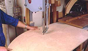
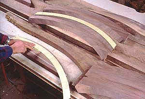
It’s only necessary to use the arcing jig to
make one of each size of template. Then use each of these to trace the others
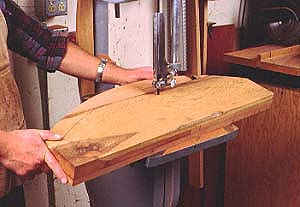
you need and cut them out on the band saw as in photo 11. Flush trim the
duplicates to size on a router table with a bearing guided router bit as in
photo 12. Smooth the surfaces that the bearings will ride on with sandpaper and
a flexible sanding block as in photo 13.
|
|
Photo 11- Band sawing out
the rest of the templates |
Your goal is to cause the router bit to swing
in a specific sphere radius on the jigs. So, you must suspend the bearing
templates above the dish or bowl with extensions that cause them to pivot from
the correct axis. The line created by joining the two pivot points on each jig
must pass through the sphere center that you are establishing. Photos 14 and 15
show how I set up each jig. Note that they are mounted atop shallow plywood
boxes. These are storage crates I’d made for something else; they were
convenient for this purpose due to their rigidity.
|
|
A full scale drawing was required for lining up
the relation between the curved templates and straight arms attached to them.
The length of the straight arms is a function of how far they are from each
other and the center of the circle. The full scale drawing shows where to align
all parts to ensure that the curved template edges are the same distance to the
sphere center along their entire length. Such a drawing is similar to drawing
3, where you are locating planes at given distances from the sphere center and
discovering where those planes intersect the sphere.
Once the templates and arms are all together,
it’s necessary to surface the dome and dish to the correct radius. The dome
gets cut to the inside radius of parts, the dish to the outside radius, so that
when parts sit on the jigs they sit "flat" and don’t rock.
|
|
Photo 13- The
surface on which the bearings ride needs to be very smooth. |
|
|
|
|
|
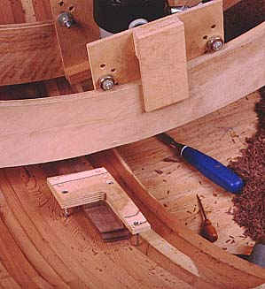
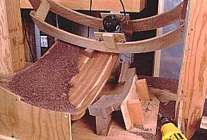
Photo 14- Dish
jig. To the right of the router is a holder jig with a frame component
mounted in it. This piece is getting its first finished curved surface cut
into it. On the left of the router is the dish glue up, on which parts will
be screwed for later operations, specifically rabbetting and mortising. Parts
can't go on this dish glue up at first, though, because they don't yet have
the curve cut into their tops to match the curve of the dish. |
MAKING
SPHERICAL SURFACES ON PARTS
The first pieces of walnut that I actually cut
were the outer frame parts for the five frames that make up the glazed portion
of the cabinet. Vertical frame components are called stiles, and horizontal are
called rails. This doesn’t apply for the top since all of its parts are
horizontal. Rail ends, however, butt onto the edges of stiles whereas stile
ends run full frame dimension.
The first curved cut made on each piece was to
dish out the inside as shown in photos 14 and 18. But it is essential that this
cut be made in correct relation to the plane of intersecting spheres. We’re
back in abstract geometry world for this. Note that there are a total of 8
corners on the cabinet where one spherical frame intersects another. There are
4 on the cabinet sides, and 4 where the top meets each of the sides. Each of
these corners represents two spheres intersecting, and therefore has a plane of
intersecting spheres. This flat plane is where the parts on the cabinet join.
Note that there are, therefore, 8 separate planes of intersecting spheres
described by the design of the cabinet.
Measuring the angle made between the plane of intersecting spheres and a
tangent to the sphere that proceeds from a point where the sphere contacts the
plane is one way to locate the relation between the plane and each sphere. But
it is difficult to implement the cuts requir
|
|
Photo 15- Dome jig. The piece of
walnut shown is getting planed to thickness. First that piece went to the
dish jig to get its inside surface brought to the curve so that it
would lie nicely on the dome as shown here. |
ed using this method. The better way to go is to determine where the plane of intersecting spheres is in relation to the main axes of the cabinet and the sphere centers, and delineate where the part resides on the plane in relation to these. Each plane of intersecting spheres has a unique angle relation to the axes of the cabinet and can therefore be measured in relation to them in terms of the angle itself and where it intersects the planes of the axes, or planes parallel to them
|
|
Photo 16- Scribing on chunks of walnut
to account for all the required frame parts. These parts have been face
jointed and planed carefully. One of the flat surfaces will remain in the
finished parts as the facet that butt joins to the adjacent frame. |
Look at photos 14 and 18. The walnut part is
screwed to a flat piece of plywood on a holder jig. The plane to which the part
is screwed is the plane of intersecting spheres for that particular part. That piece
of plywood is set at a given angle to the flat base of the jig. That base is a
plane at a given distance from the sphere center and corresponding axes of the
jig. That sphere center and the cabinet axes are drawn on a full scale drawing
(drawing ), showing their relation to the plane of intersecting spheres. The
full scale drawing, with a drawing of the holder jig and jig base plane on it,
shows you just where to locate the holder jig on the base plane such that the
dish cut is made correctly.
Confused? Remember, it took me a long time to
learn to conceptualize this stuff. The best way to learn it is to do it. Make
some full scale drawings. You’ll have fun, I guarantee it.
|
|
Photo 17- Rough cutting the parts out
of walnut at the approximate angle required. I left about 1/8" on both
sides for the router to clean up at the dish and dome jigs. |
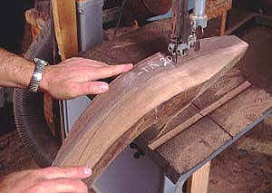
To make parts for the frames, I first face
jointed and then planed stock so that both faces were flat. One of these flat
surfaces will remain on each part and become the surface that joins the
adjacent frame on the plane of intersecting spheres. Then I made templates
showing the curves of the parts along the planes of intersecting spheres.
Computing the radii of these templates is like computing the radii of
successive layers of the jig blanks. Using these templates I traced lines onto
the flat stock as in photo 16, then cut out the parts on the band saw as in photo
17. I cut the parts out over size so that the router had something to cut, and
cut on the band saw at the required angle as shown on my drawings.
|
|
Photo 18- A frame part getting
dished out. The holder to which it is screwed is located on the plane of
intersecting spheres in correct relation to the sphere center of the jig and
frame part. |
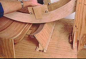
Next each part goes onto the dish jig on its
own holder jig as in photos 14 and 18. I didn’t need a separate holder jig for
each part, since some are duplicates of each other. With each part in the
holder jig I then had to be sure that the router bit in the dish jig was
lowered to a height that would produce the correct radius on the dish cut.
After all this preparation I finally began to cut dished surfaces in walnut
parts.
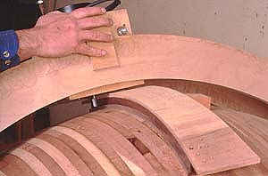
After the parts were dished, they could go onto
the dome jig as in photo 15. This cut brings the parts to thickness. Note that
in this step and many succeeding steps you don’t have to think about the plane
of intersecting spheres and all that stuff. The basic relation between the
plane of intersecting spheres and the curved surfaces was established at the
dish jig in the first step. All else follows directly from that dish cut until
you get to joining the four corners of the frames.
CUTTING PART EDGES
It would help a great deal if you understand
how cope and stick joinery is done on a flat plane before you tackle it here on
a sphere. So I recommend that you read another page on this site first, which
covers this subject. There’s no cost for it and you can link to it here.
|
|
Photo 19- After the part has been
planed to thickness, it gets flush trimmed on the inside edge. I did this in
two passes. The first one, shown here, has the bearing of the bit riding on
the template. |
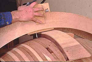
After the parts were brought to thickness, the
next step was to flush trim the inside edges of the parts on the dome jig as in
photos 19 and 20. There must be a mathematical means of establishing the radius
of curvature that you need to draw onto the flat plywood template stock in
order to make a template that, when pulled onto the curve of the parts, will
make a flush trim cut that is parallel to the other side of the part. But I
don’t know what this mathematical means is. I pulled the plywood across the part
and traced the curve from the edge of the part, then cut on a band saw and
sanded smooth. This was adequate, but with a true radius you could cut out the
template with a router arcing jig and get a dead true result.
|
|
Photo 20- Here the flush trim bit
has been lowered to complete the flush trimming operation. The bearing now
rides on the walnut freshly cut in the previous pass. Cutting these edges in
two passes this way was far easier than in one cut, where the bit wanted to
chatter badly because it was being asked to remove so much material. |
The plywood I used is called ‘wiggle wood’. It
is a special plywood that bends easily, used to make single bent cabinet
shapes.
The flush trimming cut on the edge of the parts
makes the inside edge be 90o to the faces (not exactly- more on this later). I
did it in two passes, since flush trimming a whole inch thickness at once was a
bit too much to do without chattering. Photo 19 shows the first cut with the
router bit riding on the template, 20 shows the second cut with the bit lowered
and the bearing riding on walnut.
|
|
Photo 21- Cutting
the sticking on parts at the dome jig. |
The next cut was the sticking pass, photo 21.
The sticking is the molded edge on the inside of the parts which forms the rabbet
that the glass sits in. See drawing # . The router bits I used to cut the
sticking and corresponding cope were custom made to my specs, and cost about
$500. I may have been able to use stock cope and stick bits, but I didn’t like
the way they looked and anyway they are probably too large to fit on the dome
jig without smacking into the jig itself during cuts. My bits were made by
Lemmon and Snoap, a manufacturer of custom router bits for industry. If you
have bits made, you must make a scale drawing specifying all radii and
dimensions.
|
|
Photo 22- Cutting
the rabbets on the part edges after the sticking pass. |
After cutting the sticking on all parts, I took
them back to the dish jig for the rabbetting cut, photo 22. Before doing so,
however, I set up the cope cut on the dome jig to make a few cope cuts to use
in setting up the rabbetting cut. The height of the rabbetting cut determines
the height of the sticking, which determines the fit of the sticking in the
cope cut. It was necessary to carefully adjust the exact height of the
rabbetting cut to ensure a good fit of the sticking on the cope.
JOINING THE FRAME CORNERS
Can’t let you go too long without getting into
the abstract stuff, but that’s why you’re here, right?
The next step is to make the end cuts on the
rails, which will determine the size of each frame. To determine the locations
of these end cuts, you must make full scale drawings of the separate frames on
the assembly dome (the second dome). To make these drawings, you must know the
size of each frame. The best way to refer to the size of these frames is by the
outside corners of them, that is, you must know where the outside corners are in
relation to the cabinet axes. How do you do this, when there are no rectilinear
references to measure from?
This problem was, for me, the most difficult
conceptual aspect of building the cabinet and kept me awake for several nights.
I’ll do my best to explain it here, and I hope not to confuse you. It took
numerous drawings and a lot of head scratching before I finally cracked this
nut. To understand this I suggest you make drawings too, read the text, refer
to both, then write me and tell me how I should have explained it to make it
more comprehensible. If your explanation of how my explanation was lacking is,
itself , less lacking than mine, I’ll consider posting some or all of it here.
THREE VARYING FACTORS MEAN CALCULUS
I greatly simplified this situation by
arbitrarily deciding how high above the cabinet base the top corners would be.
There are four top corners, where the sides and top meet. All four of these
points lie on a horizontal plane, which is parallel to the table top base that
the curved sides sit upon. By arbitrarily deciding that the distance from this
plane to the base was X, I avoided having to calculate where this plane was,
given the height of the cabinet at top center.
On a rectilinear cabinet the height of the
cabinet and the height of the corners are the same number. On a spherical
cabinet they aren’t. The top of my cabinet is higher than the corners due to
the spherical shape of the top. Two other factors contributing to the location
of the corners are the locations of the two sides relative to the top, and each
other. So, the location of each corner is determined by how three sphere
sections intersect. If you know the radii of the spheres and the relation of
all three sphere centers on the axes, you must be able to use calculus to determine
the corner location. However, though I think I passed calculus in high school,
I’ve forgotten it all long since.
By eliminating one of three factors I reduced
the mathematical complexity of the problem, making it more accessible to my
feeble linear thinking. I determined the radii and sphere center locations for
the sides, but only the radius for the top and not its sphere center location.
(All sphere radii for all sides and top are the same on this cabinet.) Then I
decided how high I wanted the corners to be. In effect, I was letting the top
center end up wherever it would given the fixed height of the four corners.
The next question is- where are the four
corners on the horizontal plane that they all lie upon. This I determined by
making a drawing of that horizontal plane, and scribing onto it where the arcs
of the sides intersect the plane. The intersections of these arcs with each
other locate the top corner points. The radius of curvature for these arcs that
intersect the plane is not the same as the radius of curvature of the spheres
themselves. This is because the plane of top corner intersection does not pass
through any of the sphere centers for the sides. All four of those sphere
centers reside on another plane, which is 16 inches below the top plane and
constitutes the X axis-plane of the cabinet.
We’re dealing with the same situation as with
the pieces constituting the dome and dish jigs. Each piece had to be cut on a
different radius, depending on how far the plane of the piece was from the
sphere center.
Imagine one cabinet side, then imagine the
entire larger sphere that this side came out of. Imagine a horizontal plane
passing through the sphere center, then imagine a parallel horizontal plane 16
inches above the first. This is the plane of the top corners, and it intersects
the sphere along a circle. The radius of this circle is less than the sphere
radius because the plane is a certain distance (16") from the sphere
center.
We can determine the exact radius of this
circle with a Y axis drawing of one of the cabinet sides. This drawing will
show us how much less is the distance from the sphere to the Y axis at the
corner plane than at the X plane.
Note that the same procedure for determining
the locations of the top corners works to find the locations of the bottom
corners which lie on a real plane- the base table.
MEANWHILE, BACK AT THE RANCH
Now where were we... oh yes, we had just made
all the frame parts, put sticking and rabbets on them, and we were about to do
the joinery at the rail and stile corners when we were distracted by some nasty
geometry.
When you have made the drawings of the top
point plane and base plane, and located on them the frame corners as we saw
above, you now have all of the information you need to draw the location of
parts onto the assembly dome. Making these drawings on the assembly dome is
really the only way to align the parts in each frame. I made these drawings
using large shop-made trammel points to function as a compass. The drawings of
the top and bottom planes showed me the linear distance between corners, so
with the trammel points I could draw arcs that were always a given linear
distance from the trammel center, even though I was drawing on a spherical
surface.
|
|
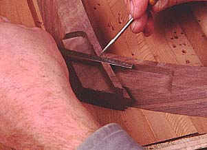
Photo 23-
Physical alignment and scribing are the only ways of accurately lining up the
parts. |
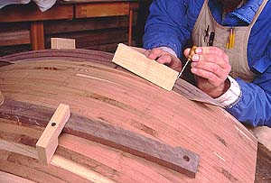
Photo 23 shows a part of the alignment
procedure. After I drew on the four corners for the cabinet top, I screwed down
the two stiles, as shown, on the lines. During the procedure I needed to
transfer marks from the dome to the top of the stiles so I could place the
rails on top of the stiles as in the next photo. But to transfer the marks I
needed to know that I was extending a true radial line. The little jig in photo
23 does that- it simply holds the end of the short piece of yellow wood at 90o
to a tangent at the dome surface, so that, by definition, the end is along a
radial.
My dog likes to read hub-caps and therefore is
frequently along a radial too, eschewing bias ply with an indignant bias.
|
|
Photo 24-
Scribing the location of rails to stiles. |
What all of this alignment is leading up to is
shown in photo 24, where the rails are placed on top of the stiles and used to
scribe onto them the line at which the stiles will eventually be cut off. When
this was done I removed the stiles and screwed down the rails on their lines,
then placed the stiles on them (like photo 24) and scribed onto the rails where
they would be cut off. Thus, final alignment for determining the frame sizes
was done by physical scribing on the pieces in this manner, rather than
abstractly measuring their length.
SHORT PHILOSOPHICAL DIGRESSION
Figuring part lengths abstractly on a project
like this is possible but very complex because you would need a means of
measuring along a curved part to a point where another curved surface
intersects. This can be done, but it’s easier to keep all the abstractions in
your head and use them to guide concrete scribings. In the old days woodworkers
used very few abstract measurements, relying on story rods and other physical
means of measure with no numerical increments involved. We, with our measuring
tapes and digital calipers may get the idea that everything needs to be
referred to a third party measuring system like inches or millimeters. But
since your object is to make the pieces fit rather than to make them fit an
abstract schema, you simplify the procedure by abandoning a third party
measuring system where it is not necessary to make things fit. I’m not saying
throw away your tape and calipers, they are time savers in many situations.
Just be willing to put them down when they are not.
END OF SHORT PHILOSOPHICAL DIGRESSION
You may be relieved to know that we are past
the majority of the abstract conceptualizing in the project. Once you have made
the parts for the frames and established the length of the parts by scribing on
them, your project is entirely committed to the specific design you have
developed. You can’t change the part lengths without altering the way they all
fit together. This is often true in rectilinear woodworking, but often not
true, too. For instance, you can decrease the height of a rectilinear cabinet
without affecting the width of the sides, front and back. Can’t happen with a
bombe vitrine. Decreasing the height of this cabinet (lowering the top) either
forces you to increase the width of the sides at the top, or decrease the
overall width of the sides.
Okay, sorry, I said we were past the abstract
stuff. The point of the above is that once you commit to a design you must
stick with it throughout. The good thing about this is that once you have all
this established as outlined above, you can leave the abstractions behind and
just have fun doing compound curve cope and stick on the frame parts and tree
branches. The bad thing is that if you blew it on the abstract stuff, you are
in for a surprise when you go to fit all the frames together. As you can see
from the photo, that didn’t happen with me.
Getting a good scribe on the frame parts is
your last operation that affects the fit of the five frames together. It’s your
last chance to double check your design and the relationship between each of
the sides to each other and the top. Misalignments now (or that exist now from
previous errors) will result in the flat portions of each frame part failing to
be aligned correctly to the appropriate plane of intersecting spheres. The
result of this is that the frames won’t fit- there will be tapered gaps where
the flat parts should mate each other.
MAKING THE FRAME JOINTS
Having scribed the locations of the ends on the
rails and stiles, the next step was to flush trim the ends of the rails, as in
photo 25. The first thing you’ll notice about that photo is that the tail end
of the rail that is clamped to the dome jig is off the jig surface. It is not
lying flat on the jig, but is tilted up. This
is intentional, for the following reason.
|
|
Photo 25- Basic
setup for flush trimming and coping the ends of rails that will butt up
against stiles. Why is the tail end up in the air? See text. |
Refer to drawing 6, which is exaggerated for
clarity. This shows the flush trimming operation on the dome jig. If the jig is
built correctly, the center of the flush trim bit will point toward the sphere
center of the dome jig. But, the cutter on the bit is a certain distance away
from the center of the bit. Therefore, the surface cut by the bit into the part
is not along a radial, which is to say that it does not point toward the center
as the drawing shows. So, when you flush trim two surfaces this way and then
try to mate them as we are trying to do with the rail ends against the stile
rabbets and sticking, the surfaces will not mate because they are not aligned
to center, as shown in the second part of the drawing.
This is an unfortunate consequence of the fact
that I chose to use router bits meant for rectilinear work with spherical work.
The mismatched joints perplexed me for a while, until I saw the geometry. Then
I realized that I either had to have customized bits produced with flutes cut
at angles that matched the geometry of my jigs, or tilt each piece as it was
cut so that the angle of cut matched. I experimented with the latter until I
found a way to do so reliably, which is shown in photo 25. There is a small
spacer under the rail, at five inches from the end being cut. So long as this
spacer was always at five inches from the end, it angled the piece just right
for a correct fit. All pieces that got a cope cut into the ends had to be
angled in this fashion, including all tree branches.
You might think that tilting parts this way is
an unreliable and inexact means of obtaining tight joints, and the fact is that
it is not an exact science. But I realized that having customized bits produced
would have been problematic. Though they would have been geometrically correct
in theory, the fact is that there was variation in the radial alignment of the
rabbets and sticking to which the rail ends and tree branch ends were being
fitted. These variations were due to the fact that the jigs were accurate but
not absolutely precise. As well, when I cut the sticking on a lot of the tree
branches (to which other tree branches would be fitted), these small pieces
were difficult to make lie exactly flat on the jigs, causing variation in the
rabbet alignment. Not much, but enough to affect the fit of copes against the
sticking. By varying the location of the tilt spacer for individual joints, I
could accommodate all such variations. The end result is that all cope joints
on the piece are very tight.
I think this is the only way to do such work
unless you build far more rigid and exact jigs that will produce parts that are
dead on geometrically correct. But at the same time, why bother making such
expensive and precise jigs, when it’s easy to custom fit each joint to
accommodate small variations? It would take far less time to make such
accommodations than to build "precise" jigs. Even if you did build
jigs that were "precise", Murphy’s law might make a fool of you and
you’d end up custom adjusting the angles of cope joints anyway. (Murphy's law-
if it can go wrong, it will). Once again, the goal is to make the joints fit
tightly, not to make the joints fit an abstract schema precisely. To my mind,
the minimum technology required to do so is all that’s necessary. After
completing the procedure I was satisfied with the degree of accuracy that the
jigs were capable of producing as built. I was willing to make accommodation
for the extent to which they were not absolutely precise, because that
accomodation was not excessively difficult or time consuming. As you’ll see,
each joint is individually cut anyway, so adding the tilting procedure was not
burdensome.
Back to photo 25. Note the small plywood flush
trim template on top of the part. This, like the flush trim template used to
make the sticking edges, should have a curve in it that matches the curve of the
stiles on the frames. This template is attached to two blocks, one on either
side of the rail being worked. These are cope blocks. They do numerous things;
they give something to screw the template to, they back up the cut on the part
to reduce tearout, and they give a surface for the cope cutter bearing to ride
on as it enters and leaves the part (since it doesn’t ride on the template like
the flush trimmer).
Important things in this procedure are to get
the flush trim template very accurately located on the scribe mark made on the
rail, and to get the cope blocks tight. The part being cut has sticking cut
into it on one edge, so the cope block that butts against this edge must have a
cope profile cut into it, and this cope profile must fit the sticking so
tightly at the point of cut that it pinches it to prevent tearout. You’ll see
more on cope cuts when we get to the tree branches (look ahead at those
photos).
SPHERICAL LAPPED TENONS
I considered using dowels to join the frames-
for about three seconds. Yes you could make special dowel jigs that align the
holes correctly etc., but I don’t want to be the one who does it. The lapped
tenons shown here could be made with the jigs as they were, and a tenon beats a
dowel any day. Each joint consists of three pieces lapped together. The tenon
is a loose spline that bridges the joint and joins the pieces, the two pieces
on top of the tenon simply cover it over to support it and complete the
structural integrity of the joint. It was necessary to lap the pieces because I
could not cut a spherical mortise without buying a customized router bit
manufactured at the correct radius. That is, I suppose, a viable option. The
laps, however, were easy to make (if time consuming) and worked quite well.
|
|
Photo 26-
Mortising cuts in the rails and stiles were done with a simple flush trimming
jig like so. |
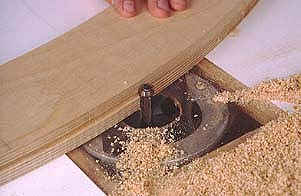
The procedure required cutting two levels of
mortises, the lower for the tenon itself and the upper level for the lapped
laminations that cover the tenon. Photos 26 and 27 show the flush trim template
used to cut these mortises.
|
|
Photo 27- By
cutting the mortises in the dish jig they followed the spherical shape of
everything else. |
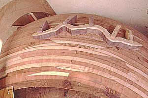
A little hand work was required to complete the
joints as we see in photo 28 where a little wall must be scribed to the line of
its adjacent lap and then removed by hand with a chisel.
|
|
Photo 28- A bit
of hand work was required to finish up the mortises. |
The tenons themselves were made with procedures
very similar to those used to make the parts for the frames. First each tenon
was dished out to the internal radius, then placed on the dome jig and brought
to thickness. Then at each joint the three pieces had to be custom fitted to
the mortise edges and shoulders. The following photo sequence (photos 29-33)
shows how the joints go together.
|
|
Photo 29- The
completed joint and spherical tenons ready for assembly. |
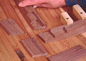
Photo 29 shows the completed joint ready for
assembly. Note that the joinery has removed most of the cope joint, but that it
does remain on the inside corner where it will be seen.
|
|
Photo 30- First the rail is butted up against the edge of the stile
with the cope overlapping the sticking. |
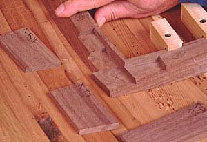
Photo 30 shows the cope of the rail brought
onto the sticking of the stile.
|
|
Photo 31- Then the tenon is put in place, bridging the joint between
rail and stile. |
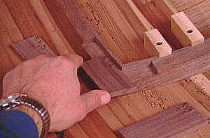
Photo 31 shows the tenon in place in the lower
mortise.
|
|
Photo 32- Next the first of two top plates goes in place to
cover the tenon. |
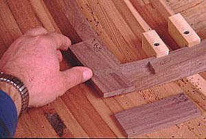
Photo 32 shows the first top piece placed over
the tenon and rail.
|
|
Photo 33- The second of the top plates in place, completing the joint. |
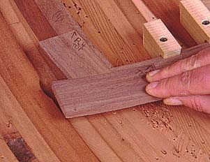
Photo 33 shows the second top piece in place
over the tenon and stile.
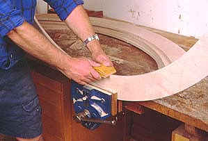
GLUE UP
Each frame was then glued up on the assembly
dome as shown in photo 34. I wetted out the tenons and laps, put it all
together on the drawn lines on the dome, and clamped it together with special
screw blocks as shown. When out of clamps, I brought the tenons flush with the
rail and stile edges on the jointer, a procedure for experienced jointer users
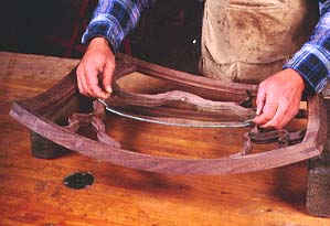
only. The big test came when I took the five frames and taped them together to
see how well the edges were aligned to their respective planes of intersecting
spheres. All were close, few were exact, and I ended up using a block plane for
final fitting. But they were close enough that this fitting was not too
difficult. That was a big relief.
|
|
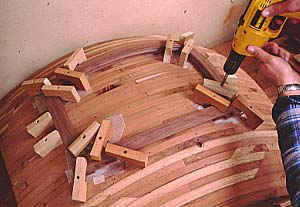
Photo 34- Gluing
together the top frame on the assembly dome. The tenons and plates are all
neatly tucked under it all and compressed by pressure from above with the
screw blocks. |
MAKING TREE BRANCHES
The nice thing about making the tree branches
that fit in the frames is that there are no planes of intersecting spheres to
worry about, or other complex geometrical issues. All of that is taken care of
by the jigs- if they are set right and you know how to use them it’s just a
matter of making parts. This is nice because it leaves you to focus on the most
visible aspect of the finished cabinet- the fit of the cope and stick joints
between the pieces constituting the branches.
I began with an outing one fine sunny day to
photograph the branches of native oak trees here in California, specifically at
the University of California at Santa Cruz, my alma mater. Using slide film I
got as many shots of well-shaped branches as I could, then using a slide
projector I put these photos up on the wall. Next I taped large pieces of paper
to the wall and began tracing out possible forms. My first set of drawings was
very bad- too many branches and not enough glass. It is, after all, a display
case. The next set is what you see, more glass and carefully proportioned trees
and branches. I didn’t trace whole trees from the slides, rather I patched bits
and pieces here and there, as well as making my own sketches where necessary.
But Mother Nature is a better artist than I and she is author of most of the
branch shapes.
|
|
Photo 35- A tree
branch glue up being dished out in step one of its procedure. It doesn't need
to be held in any relation to any plane of intersecting spheres since it
intersects no other sphere, at least not in my cabinet. |
Next I used my final set of drawings to trace
out templates for each branch. Placing the paper on top of wiggle wood plywood
I punched through it with a sharp nail along the lines, then removed the paper
and traced along the nail holes. After band sawing out the piece I took it to
the drill press with a small drum sander and smoothed the edges a bit.
|
|
Photo 36- Planing
the branch to thickness. |
Each tree branch started as rough wood on the
dish jig. Since there is no plane of intersecting spheres to worry about, the
first cut is not a flat plane as with the frame components. I needed to glue up
some pieces first, though, to get the curves needed for longer parts. These
glue ups were all guesses in terms of how much wood to use and at what angle to
glue them, but they all worked out.
|
|
Photo 37- One side of the tree branch getting fluzh trimmed to the
shape of the template. |
Such a glued-up piece is shown in photo 35 in
the dish jig. It’s held in place just well enough to establish the dish
surface. Then it moves to the dome jig as in photo 36 to get planed to
thickness. Next the template goes on it for tracing, then to the band saw with
a spherical support fixture (not shown) to cut off the waste. Then back to the
dome jig as in photo 37 with the template clamped in place for the flush trim
pass.
|
|
Photo 38- A different tree branch after the sticking has been cut into
it, and before it gets the rabbet at the dish jig. |
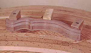
Photo 38 shows a different piece set up on the
dome after the sticking has been cut. Note that the template is no longer
there, because the sticking cutter bearing rides on walnut, not the template. I
made a lot of special little wooden keepers to hold parts down at each step.
After each part got the sticking it went back to the dish jig for a rabbet,
similar to photo 22. At this point the parts were done, except of course for
making the joints on the ends.
FITTING THE BRANCHES
The first step on fitting the branches was to
place each frame over the drawings I had made of the branches in the frames,
and deciding the order in which the parts would be assembled. Then I marked the
frame at the locations where branches intersected the frame itself. Next, I
placed the first branch to be fitted on the assembly dome, and placed the frame
over it at the marks. Now I traced the line of the rabbet from the frame onto
the branch. This, however, was an inaccurate tracing in all cases.
Because the frame is sitting on top of the
branch, the inside surface of the frame is sitting on the outside surface of
the branch. But the inside surface of all parts has a different sphere radius
than the outside surface. The rabbets are closer to each other because they are
closer to the sphere center. So, while my scribe marks did show the correct
angle to make the end cuts at, the scribe marks were too close to each other,
describing a part that is too short. In all cases I had to lengthen the parts,
proportionately as they were long. This is another unfortunate consequence of
my decision to make spherical rather than rectilinear parts. Lucky for me I
only wasted one part before I figured out what was going on.
|
|
Photo 39. Set up for coping the ends of the parts. The part must be
held in place solidly, and have cope blocks on either side of it that fit
tightly against it. |
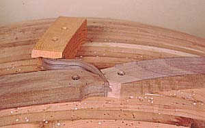
Photo 39 shows the initial setup for a very
small branch. The branch is tilted with a spacer that you can’t see. It’s held
down with a special keeper (the yellow piece behind), which was used on every
single branch bar none. But, every branch had to have its own set of cope
blocks custom made to accommodate the shape of the branch and the angle at
which it was cut. I was able to re-use some cope blocks but rarely could they
be reused without some modification, at least at the band saw. The cope blocks,
as you see, have the cope profile cut into their ends so that those ends can be
fitted over the sticking on either side of the branch. The cope blocks are
pinched tight to the branch, then screwed down as shown.
|
|
Photo 40- The appropriate coping flush trim template is placed across
the top of the pieces along the line scribed on the branch. |
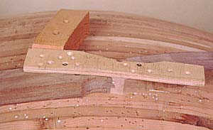
Photo 40 shows the flush trim template in
place. It is a straight template because this end intersects a frame stile. But
where branches intersected curved parts on other branches the flush trim
template had to be custom made to the shape of the curve of the rabbet on the
part being fitted to. I traced these, cut them on the band saw and smoothed
them with a drum sander on the drill press. The accuracy of these templates was
critical to the fit of these joints, and I had a few failures that had to be
redone.
|
|
Photo 41- The only
difference between this shot and the last is that the flush trimming has been
done and now the surface is smooth. |
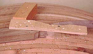
Photo 41 shows what the piece looks like after
the flush trimmer has cleaned up the end of the part.
|
|
Photo 42- After the cope. The importance of the cope blocks should
be evident here. The bearing of the cope cutter needs a surface to ride
on coming into and going out of the cut so that the whole cut stays properly
aligned. The cope cutter bearing is not riding on the template, which is
superfluous at this point. The cope block on the right must pinch the
sticking to avoid tearout as the bit comes out of the cut. The cope block on
the left needn't pinch, but must be close to give the bearing a surface to
ride on. |
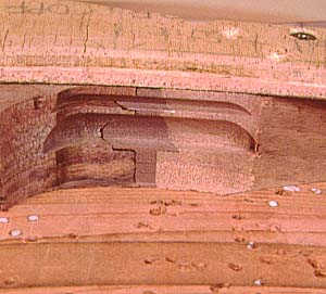
Photo 42 shows the cope cut. I had the cope bit
in a separate router and carriage so that I could pull the router carriage with
the flush trimmer out of the template arms on the jig, place the cope carriage
in, and cut. This is necessary because you are constantly alternating between
flush trim and cope cuts during this fitting operation.
As each branch was completed I glued it in
place before fitting others that would be attached to it. This allowed me to
alter its location during glue-up slightly from what was intended, allowing me
to fudge the fit and locate the piece where the joints were tightest. As well,
it’s best that the parts are glued in place when you do the alignment procedure
for successive pieces so you know exactly what you are aligning to.
When the branches were all glued into the
frames I began a long and tedious scraping and sanding procedure on them.
Looking at the door, I realized it would be best if it lay against a wider
piece rather than the edges of the adjoining frames, so I made the flat spacers
that fit between each of the frames. Note that these spacers intersect, three
at a time, at the four top corners. Each of the three at each joint required
two compound miter cuts. You might think that one compound miter cut would do
all six so long as it was divided by 360o, but no. I had to make six separate
compound miter jigs, a separate one for each facet. I didn’t bother trying to
figure the geometry involved here, I simply used ‘cut and fit’ until they did.
The door has no hinges. The butts of the
hinges, if used, would have to stick out very far to clear the curve. So, the
door simply pops off. It rests on two brass pins at the bottom and has a lock
up top so that it can be secured.
GLASS BENDING
Hooray! All the parts are machined at correct
radii and fitted with tight cope joints. Now all we gotta do is get some glass
in it. Unfortunately, all the glass down at the local supplier is flat as
Glass kilns are expensive but essential because
you must control the conditions very carefully when the glass cools to keep it
from shattering. Fortunately though, simple bending of thin sheets of glass is
about the easiest procedure you can do in a glass kiln. You must make an
accurate mold with a refractory cement, which is none too expensive or
difficult. You must learn enough about the mechanics of heat gain and loss in
glass to know that you are annealing the glass correctly (cooling). This,
however, is not complicated. With these tasks under your belt, making bowls of
glass at a very accurate radius is very easy. Cutting the bowls into the shapes
that fit your wood will require a ring saw if the edges are irregular as in my
vitrine. Ring saws are like band saws but have a 6" rigid ring instead of
a flexible band. They cost $250 or so.
I researched having the glass bent by others,
but finally realized that this would be very expensive because they would have
to make a mold. The glass must be bent to a very accurate radius of spherical
curvature, requiring such a mold. It’s easy to free-slump the glass, but
inaccurate. ‘Slumping’ is a general term for heating glass in a kiln and
allowing it to ‘slump’ down by gravity onto a mold or whatever to achieve a
certain shape. ‘Free-slumping’ is my term, for doing slumping where there is no
mold.
Experimenting with free slumping to get my
bowls of glass, I took metal rings and put flat glass on them in the kiln. I
cooked it to where the glass began to slump into the ring, and stopped the
slumping when the glass had fallen to the depth required. But the resulting
bowls were not accurate sphere sections. Free-slumping cannot produce the
degree of accuracy required to fit larger pieces of glass to wood, but it could
work if no piece of glass must be larger than 10" diameter or so. When you
slump smaller bowls to a slight drop, they approximate a sphere well (when
dropped in a circle), but the larger the diameter you try, and the deeper the
drop, the less accurate it becomes.
Fortunately making a mold was easy once I
located the right mold material. Dan Fenton is a glass magician who lives in
Beware of mold formulations you may find in
glass working books. Most of these are for glass casting situations where it is
essential to the procedure that the mold material be broken away from the glass
casting after the cast has cooled. These mold materials must be strong enough
to be cast into at high heat, but weak enough to be broken away later. You
don’t want this. You want a mold that is strong as possible and that will not
distort its shape in the process of making it.
Beware of making clay molds. All clays shrink
as they dry and shrink again when you put them in the kiln for the first
firing. They will not hold the accurate shape you need to make spherical bowls.
You can have a cast iron mold made for $750,
but why bother when a few bags of castable refractory cement are less than
$100? The reason would be if you needed a mold to use over and over, because a
mold made of refractory cement will not hold up for as many firings as a cast
iron mold. But a cement mold will hold up for the several dozen firings needed
for one cabinet.
MOLD FORMING
Because the radius of curvature of the glass
was different than either the dish or dome jigs, I had to make a separate dome
jig for the purpose of casting the bowl-shaped mold. This wood jig is called a
former, because its shape accurately forms the mold. I learned an important
lesson about making accurate glass molds here. You can make a mold using a
former, or you can make a mold without a former. But the latter doesn’t work so
you have to use the former.
With the former made, I covered it with wax and
then a 2" thick layer of Greencast, and then worked wire mesh into it for
additional strength. When wet, the Greencast had an unusual quality to it,
unlike Portland cement. It was rubbery, spongy, almost elastic. Quite unusual.
After it set up, I pulled the mold off the former and let it sit for days
before sticking it in the kiln. Before you can use such a mold you have to get
rid of the excess moisture in it. If you do so too quickly in the kiln, it will
explode as steam pressure builds up inside. Time is the key.
When I did put it in the kiln, I heated it
very, very slowly, over almost two days to a temperature of 800 degrees (F- I
use no Celcius here). I was amazed to see that even above 600 degrees moisture
was being driven from the piece as condensation continued to form around the
kiln lid when opened. This, I suspect, was chemically bound moisture that
required the higher heat to drive it off, but I don’t know for sure.
You must use a separator on anything that hot
glass will contact in a kiln. Separators are powders or pastes of high heat
materials that don’t stick to glass, and prevent the glass from sticking to
molds or whatever else it touches. I used a zircon-graphite paste separator
used by bead makers, but discovered that the mold required very little, if it
ever needed any at all. Calcium alumina is interesting stuff.
GLASS AND HEAT- SLOW MOTION
Glass is a weird substance- not a liquid or a
solid, it acts a little like both. This is due to its unusual molecular
structure. What you need to know is that heat moves slowly through glass, and
if you let the temperature difference between one area of a piece of glass and
another get too great, it will break. This is because as glass heats it expands
and as it cools it shrinks, and, unlike other materials it is brittle. So, if
one part of the glass is trying to expand or contract while another is not,
what happens to the area between them that is getting pulled in two directions?
It breaks, unlike metals which are flexible and so just bend to compensate.
The thicker the glass the worse the problem.
Thin glass, like the 1/8" thick GNA (German New Antique) I used here is
easiest to use. Still, you must be sure you don’t push the glass too far for
its thickness, or else.
As you heat glass in a kiln, you must heat it
slowly enough that the difference in temperature between the outside surface
and the inside mass does not become too great. You have to let the inside catch
up with the outside. Once the glass gets to a certain temperature though, it no
longer matters because the glass is soft. Then you crank the kiln full bore to
the temperature you need to get the glass to do the work you want. Then, once
the work is done, you begin to cool it. Now you must anneal the glass, which
means lowering the temperature of the glass slowly enough through a certain
temperature range that severe stresses do not develop in the hardening glass.
These stresses will develop if the outside surface cools and shrinks much faster
than the inside mass. These stresses will be permanently frozen in the glass
once it cools, if it doesn’t break to begin with, and make it harder to cut
reliably. The annealing temperature range is different for different types of
glass. Once you are below the annealing range you can cool the glass faster
because you cannot add permanent stress to the glass anymore, but you can still
break it by cooling too quickly.
I used a kiln with a digital controller, which
automatically ramps the temperature up or down at a rate that you set. With
thin glass you don’t need this if you know what you are doing, but until you do
it’s best to use a controller, go by formulas and exceed them for safety.
TRIAL AND ERROR
Glass working is an empirical science, which
means that what we know has been learned much more by trial and error than by
abstract ideas. You must, however, understand the abstract ideas behind heat
gain and loss with glass to a certain extent or else. Still, every different
glass working operation has its own peculiarities depending upon what you are
doing and how. Case-specific problems require case-specific solutions, usually
depending upon the ability of the operator to understand the problem and find a
way around it. As far as the glass is concerned there is no problem. It just
happily bends away or shatters depending upon the situation it finds itself in.
You are the one who is contriving to make it bend this way or that, and come
out of it whole without excessive stress. You must arrange the situation so
that the glass happily does what it will in a situation that will produce an
acceptable result.
I ran into a couple of problems. On my first
try, I put a piece of glass on the mold and began heating. I heated it fast
because you can do that with thin glass being heated from two sides. But when I
took a peek at 250 degrees, I saw that the glass was bending upward, away from
the mold, and severely too! What was happening was that the mold was acting as
a heat sink, so that the top of the glass was being heated far faster than the
underside which faced the mold. So, it bent up as the top expanded faster than
the underside. The glass was having so much fun arching its back while I was
sweating buckets for fear it would shatter. The solution was to slow the rate
of increase radically so the underside could catch up with the top. Once it was
toward the top of the annealing range it flattened out and I could crank it
from there.
Then, the glass began to slump into the mold.
But, the air between the mold and glass had no way to escape. So, the highly
plastic hot glass sort of bubbled up in spots rather than lie flat on the mold.
It was having lots of fun lounging on a soft bed of compressed air. I was
groaning the loss of expensive glass. That piece of glass was wasted, after
which I drilled holes in the mold for air to escape. All subsequent pieces
slumped correctly with no problem, once I let the glass do what I wanted it to
do.
|
|
Dropping glass into a hole. Note that the rabbets of the wood point
inward. This means that the opening of the hole on the inside is lesser than
at the point where the glass resides. If you scribe the glass by the shape
defined by the inner rabbet, the glass will be too small. One more nagging
problem. The bigger the glass, the worse the problem. I carved some rabbets to make way for glass. |
I then used a ring saw to cut out the separate
pieces of glass that went in each of the 32 holes in the wood. Ring saws are
glass and lapidary machines with a 6" diameter wire ring impregnated with
diamond that spins in place like a band in a band saw. You can cut glass in
360o with this tool, it just grinds away at it any direction you push.
Contact me if you need more advice on glass
bending, but only if you have spherically shaped wood frames to put it in!
A SIMPLER CABINET
Perhaps you want to build a simpler cabinet
that uses a spherical frame. Here’s an idea.
Design a rectilinear cabinet which has only the
front bowed into a spherical shape. The sides, top, and back are all flat. You
will have no planes of intersecting spheres to worry about, but you will have
to properly align the flat edges of the spherical frame where it contacts the
flat sides and top. This is explained above in the discussion on how the frames
intersect the table base of the cabinet.
Don’t use specialized router bits, just use
rabbeting cutters and you will end up with a square sticking. The joints
produced won’t be as strong as true cope joints but you can epoxy them.
Keep the size of the pieces of glass small so
you don’t have to slump 27" diameter bowls like I did. There are plenty of
ceramic kilns in the world, and if you make a mold you will probably be able to
find a sympathetic potter or glass worker that will slump it for you at a fee
or let you do it. Smaller kilns are not too expensive, and you will get by
without a digital controller if all you do is 1/8" glass.
If you do this, don’t hesitate to contact me
for advice, but ONLY if you seriously do it, not just if you dream about it,
please. I’ve done enough spherical compound curve cope and stick joinery
dreaming for one life time- now I want to see results.